Introduction - N9XG

We're building an RV9A together. The tail number is already reserved and is "N9XG"

It's the biggest project either of us has ever started. We're having a lot of fun and learning many things about airplane construction and about ourselves as well. This site is about the process, and our progress.

We will be updating this from time to time with progress reports. If you can't see enough detail in any of the pictures you can click on them and they will expand (like Magic).

Saturday, January 30, 2010

A visit to Catto propellers

My wife and I drove from Olympia to San Diego to take a cruise with the family in December. On the way South, I decided to drop the prop off at Catto Propellers to have the spinner cut for it.

If you don't know where Mokelumne Hill, CA is; it roughly East of Sacramento. I had purchased a Tom Tom GPS to aid with my land navigation. I'm glad I did as it was able to guide me to the trail head of the one lane winding road that took us eventually to the factory. It's about a 15 minute drive once you find the trail. Here is what the terrain looks like.


My cell phone had lost contact with civilization and the GPS said I had left the road. So I wondered as I kept going up this winding ice covered road what I would do if something happened. Visions of survivor man were tripping thru my head. Can I start a fire?... I digress.
Anyway I had faith and wanted very much to meet Craig and visit the birthplace of our beautiful propeller.


I had found the entrance, but didn't have the code to open the gate.
Did I mention my cell phone was useless?
Fortunately, the neighbor let me use his land line to contact Craig and he let us in.

I don't think they get many visitors up here.


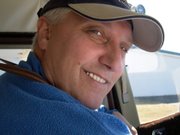
Since it's people that are really important let me introduce Craig.
Craig is very kind and knowledgeable.
He explained to me that he is in the process of expanding his operation to keep up with demand.
Each of the clipboards you see on the walls represents a propeller order.


There are two full time employees at Catto.
Nadine is the office manager.
She has been very helpful to me.


Manny is the wizard's apprentice and works in the factory.


Here are some of the rough-cut wooden cores.
After they are worked down to their finish cross section, there are two layers of carbon fiber and four layers of fiberglass applied.
The finished product is light, strong, and efficient.
Craig was telling me that many of the racers use his propellers.


As a part of the expansion, Craig was showing me this apparatus which is used to create a 3D digital model of the airfoil.
This will then be used to direct a three axis router.
This should ensure that every prop is exactly to spec and do it quickly.


So we left the propeller there and continued on to our vacation cruise.

On our way back, Manny was kind enough to meet us at the trail head
with our prop, spinner and extension plate.

Here's another VAF siting.
I am glad we took the side trip.


Our party included nine adults and seven grandkids.
Having the whole family together (for me)made it the best cruise so far.

Engine has arrived


I approached Gerber Collision and Glass about the possibility of having the engine delivered to their loading dock. I'm pleased to announce that Kirk was willing to do that. Very kind! In talking with him I think that he has an love of flying too. He seemed keen to talk airplanes with me.


Anyway, I called for a few volunteers to help with the lifting.
Here they are:Boyd on the right, Rich in the foreground and Bob in the blue jacket on the left.
While I was gathering timbers to slide it into the truck, they just picked it up and set it in.
From Gerber's loading dock to the Brooks Aircraft factory floor took only twenty minutes. I was there to help take it off the truck. Take it from me; it's HEAVY.


Bob and I spent some time looking through all the printed material and assorted parts.

Wednesday, January 6, 2010

Brake return springs installed


I saw this mod on another builders site and on RivetBangers and liked it. It was simple to implement and only cost 12$ for the materials to do all 4 brake cylinders.


These are the McMaster part numbers and descriptions:


6389K625 - NYLON BEARING, FLANGED, FOR 3/8" SHAFT DIA, 1/2" OD, 3/8" LENGTH
9657K115 - STEEL COMPRESSION SPRING, ZNC-PLTD SPRING-TEMPERED, 3" L, 1/2" OD, .047" DIA
9946K13 - ALUMINUM SET SCREW SHAFT COLLAR, 3/8" BORE, 3/4" OUTSIDE DIAMETER, 3/8" WIDTH


This is how they look assembled. You'll notice that I also replaced the multiple washers with a piece of round UHMW I purchased. The material is very cheap and fairly easy to work with. I simply measured how long it needed to be and then drilled the appropriate size hole and cut to length. If I do say so myself, I think it way cooler than 4 or 5 washers looking like we really weren't sure what we were doing.

Last night I noticed that the elevator push rod was in a bind with the flap actuator attachment.
There were two different parts that could be used for this. We cogitated over them and chose the one we thought looked stronger without realizing the bind it would create. I took remedial action and removed the extra material.

Not a problem, but I'm glad I caught it.


Proceeded laying up the the tunnel cover F-741B.
I confess with humility my envy when I read of other builders spending two hours for some major task.
Then this little cover takes us the better part of an evening.


Here Bob does the countersinking.


And voila; the finished product.


Engine is ready to ship. Unfortunately, I need to have a loading dock to get it delivered to Olympia. Otherwise, they want me to pick it up in Tukwilla (45min drive).
I think I'll have to find a loading dock.

Before we decided to build an RV9A we were looking at the RV7A. This picture was taken on a factory tour.

Standard (aka Slow build) RV9a kit

Standard (aka Slow build) RV9a kit

Quick build RV7 kit

Quick build RV7 kit

The Process

Most of us think of the airframe as the main thing, and I suppose it is; since you can't fly without it. The kits that Vans sells are match hole punched. That means that the holes are already located and punched when you get them. This saves a lot of time as you can imagine. So what follows is what you do once you've unpacked and inventoried the parts from the factory.

There are several thousands of these planes flying. Rather than making mistakes first-hand, I recommend looking at the web sites of builders who have already done this. Some of my favorite links are provided. You should also look at Van's 'Links' page for the model you're building.

Before touching the parts, it is advisable to read the instructions and review the drawings until you have a clear idea what needs to happen and what sequence it needs to happen in. The drawings are invaluable.

Each sub assembly requires the same basic process:

1. Prepare the parts for fitting. This entails cleaning, filing, and finally scotchbrighting. In addition, some parts require fabrication and/or machining.

2. Fitting is done numerous times. The pre-punched holes are matched to the corresponding part(s) and are held together with clecos.

3. Match drilling is done in assembly to provide optimum fit.

4. Once the holes are match drilled to the proper sizes, the part is disassembled and deburred to remove any sharp edges and irregularities that might result in a poor fit or the development of a crack.

5. Rivets that will be flush with the skin require either a dimple or countersinking. This is normally obvious, but sometimes the rivet needs to be flush and it's not clear at first glance just why.

6. At this point, a coat of primer and (in some cases) paint is applied protect the metal from corrosion. We've decided to prime and paint all skeletal parts; i.e. Spars, Ribs, etc. Skins will be primed where they connect. The method to our madness is this; we want defects to appear first in the skin where they are easiest to fix and pose less of a threat.

7. This is a dangerous part of the process because you might want to rivet something. But WAIT! Review the plans and the directions again.

8. Okay, so you've reviewed the plans and the parts are ready to assemble. Double and triple check the plans to ensure that the proper rivets are used. It's easy to mess this up or get out of sequence.

Rivets and Riveting

There are thousands of rivets that hold the plane together. Since this is an important task, let's talk a bit about them.

The rivets we'll be using are made of aluminium and are set in one of several ways; Hammering, Squeezing, Pull through.

Hammering a rivet is best done with a partner. One person operates the rivet gun and the other holds a bucking bar on the back side to create a shop head. I've tried doing this alone and almost always with undesirable results. The idea is for the shop head to be approx 1.5 times the diameter of the shank of the rivet.

Squeezing a rivet requires a special tool and is my preferred way whenever possible. Some folks use a manual squeezer, but I like pneumatic squeezer. They develop approx 3,000 pounds of force in the last 1/8th inch of the piston's travel. So proper adjustment is important. Once adjusted properly it will deliver consistent rivet sets.

Pull through
(aka Blind or Pop) rivets are for those applications where there is no way to get access to the back side of the rivet. In general this type of rivet has inferior strength characteristics compared to a solid rivet. The noteworthy exception is the Cherry Max rivet. It is a pull through rivet, but it is also structurally rated and not cheap.

Removal
When rivets are set badly (as is sometimes the case) You need to decide if it's so bad that it just has to be replaced or is it okay as is.   The main concern is to remove the offending rivet without doing damage to the hole it's in; e.g. enlarging or elongating or both.    

If it just doesn't pass muster, get a drill bit about the diameter of the rivet shaft or smaller. Center punch the head of the rivet (solid rivets only) and then carefully drill thru the head  just down to where the shaft meets the hole. Once this is done, insert and old drill bit into the hole and wiggle the head until it snaps off.  Once the head is off you should be able to push it out with a punch.

With pull through rivets this can be problematic, as the shaft is most likely steel and may turn with the drill bit.  Another problem with removing blind rivets is this.  Blind rivets are used because access to the back side is either difficult or impossible.  Onc you commit to removing the blind rivet, you have to figure out how to remove the back side when you punch it thru the hole.