Introduction - N9XG
We're building an RV9A together. The tail number is already reserved and is "N9XG"
It's the biggest project either of us has ever started. We're having a lot of fun and learning many things about airplane construction and about ourselves as well. This site is about the process, and our progress.
We will be updating this from time to time with progress reports. If you can't see enough detail in any of the pictures you can click on them and they will expand (like Magic).

Tonight we mounted the flaps and ailerons to see how they fit together and that the alignment is good. It is! We were both very pleased with the fit.
Bob set the length of the aileron push rod and I assembled the connecting hardware.
Here you can see the bell crank in the left wing and how it connects to the main push rod and the aileron push rod.


It always feels good to be able to say "That's done". Well the gap fairing is done. We used just about every type of rivet doing it. Sollid rivets were called for, but with the quickbuild wings it was difficult to buck them in some places. So we started using cherry max rivets. They work great especially if you get the right length. If you use the wrong length you get experience at drilling out rivets that like to spin... argh. Then we decided that since the gap fairing isn't really structural, we didn't need to use the expensive structural pull thru rivets; instead we used the LP4-3 cheapie pull thru rivets. In the picture above you can see a solid rivet on the right and two cherry max rivets to the right.
After we finished with the fairing we moved on to installing the Tru Trak servo in the right wing. Here's a picture. You can click on it if you want to see a bigger image.

We left most of the connections loose because we are not sure that they are correct. The directions are not very clear. So we will be calling the fine folks at Tru Trak to ask some questions. We also fiddled around with fitting the right aileron. We are thinking we want to get it painted before we commit to installing. All the little washers and spacers are difficult to install and we would like to not do too many iterations of putting it on and taking it off.
Had a little time this afternoon so I went out and cut the four pieces of angle that the rudder pedals are attached too. I think the part number is f6117c, but I'm working from memory here. These were super easy pieces to make; just cut four pieces 4 pieces long. I probably spent an hour doing that and polishing up the welded end on my new aileron push rods(Thanks Doug Drees).
I ordered cherry max rivets from Pearson's on Friday. They should be in Monday, so I can install them. Unfortunately they are not cheap.
The Process
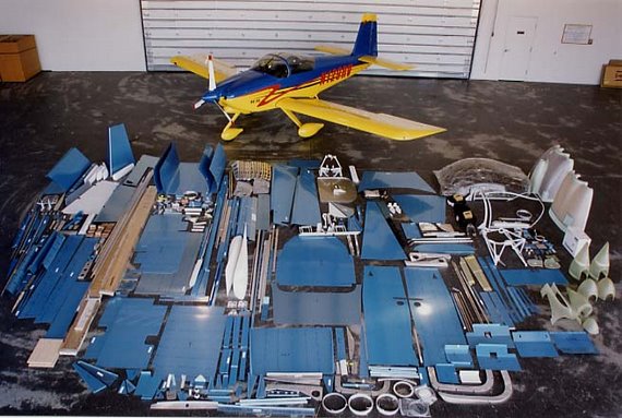
Most of us think of the airframe as the main thing, and I suppose it is; since you can't fly without it. The kits that Vans sells are match hole punched. That means that the holes are already located and punched when you get them. This saves a lot of time as you can imagine. So what follows is what you do once you've unpacked and inventoried the parts from the factory.
There are several thousands of these planes flying. Rather than making mistakes first-hand, I recommend looking at the web sites of builders who have already done this. Some of my favorite links are provided. You should also look at Van's 'Links' page for the model you're building.
Before touching the parts, it is advisable to read the instructions and review the drawings until you have a clear idea what needs to happen and what sequence it needs to happen in. The drawings are invaluable.
Each sub assembly requires the same basic process:
1. Prepare the parts for fitting. This entails cleaning, filing, and finally scotchbrighting. In addition, some parts require fabrication and/or machining.
2. Fitting is done numerous times. The pre-punched holes are matched to the corresponding part(s) and are held together with clecos.
3. Match drilling is done in assembly to provide optimum fit.
4. Once the holes are match drilled to the proper sizes, the part is disassembled and deburred to remove any sharp edges and irregularities that might result in a poor fit or the development of a crack.
5. Rivets that will be flush with the skin require either a dimple or countersinking. This is normally obvious, but sometimes the rivet needs to be flush and it's not clear at first glance just why.
6. At this point, a coat of primer and (in some cases) paint is applied protect the metal from corrosion. We've decided to prime and paint all skeletal parts; i.e. Spars, Ribs, etc. Skins will be primed where they connect. The method to our madness is this; we want defects to appear first in the skin where they are easiest to fix and pose less of a threat.
7. This is a dangerous part of the process because you might want to rivet something. But WAIT! Review the plans and the directions again.
8. Okay, so you've reviewed the plans and the parts are ready to assemble. Double and triple check the plans to ensure that the proper rivets are used. It's easy to mess this up or get out of sequence.
Rivets and Riveting
There are thousands of rivets that hold the plane together. Since this is an important task, let's talk a bit about them.
The rivets we'll be using are made of aluminium and are set in one of several ways; Hammering, Squeezing, Pull through.
Hammering a rivet is best done with a partner. One person operates the rivet gun and the other holds a bucking bar on the back side to create a shop head. I've tried doing this alone and almost always with undesirable results. The idea is for the shop head to be approx 1.5 times the diameter of the shank of the rivet.
Squeezing a rivet requires a special tool and is my preferred way whenever possible. Some folks use a manual squeezer, but I like pneumatic squeezer. They develop approx 3,000 pounds of force in the last 1/8th inch of the piston's travel. So proper adjustment is important. Once adjusted properly it will deliver consistent rivet sets.
Pull through (aka Blind or Pop) rivets are for those applications where there is no way to get access to the back side of the rivet. In general this type of rivet has inferior strength characteristics compared to a solid rivet. The noteworthy exception is the Cherry Max rivet. It is a pull through rivet, but it is also structurally rated and not cheap.
Removal
When rivets are set badly (as is sometimes the case) You need to decide if it's so bad that it just has to be replaced or is it okay as is. The main concern is to remove the offending rivet without doing damage to the hole it's in; e.g. enlarging or elongating or both.
If it just doesn't pass muster, get a drill bit about the diameter of the rivet shaft or smaller. Center punch the head of the rivet (solid rivets only) and then carefully drill thru the head just down to where the shaft meets the hole. Once this is done, insert and old drill bit into the hole and wiggle the head until it snaps off. Once the head is off you should be able to push it out with a punch.
With pull through rivets this can be problematic, as the shaft is most likely steel and may turn with the drill bit. Another problem with removing blind rivets is this. Blind rivets are used because access to the back side is either difficult or impossible. Onc you commit to removing the blind rivet, you have to figure out how to remove the back side when you punch it thru the hole.


 We left most of the connections loose because we are not sure that they are correct. The directions are not very clear. So we will be calling the fine folks at Tru Trak to ask some questions. We also fiddled around with fitting the right aileron. We are thinking we want to get it painted before we commit to installing. All the little washers and spacers are difficult to install and we would like to not do too many iterations of putting it on and taking it off.