I got fed up with this not flying thing. So I went in and hired a CFI to help me make sure I'm still safe. We did about 1.5 hours on the ground and 1.8 in the air. I was pleased to still know what to do.
So I reserved a plane for Saturday to fly to Scappoose. Then this morning the weather was marginal and so was my health. I decided to stay on the ground today.
Saturday, June 19, 2010
Sunday, June 6, 2010
Wrapping up the Roll bar
We've gotten the roll bar all riveted together, and now we are working on the custom fit with the brackets. Here are a few shots of the process.

First we started by clamping the parts to a rigid board. Then we secured the parts to the board with clamps and clecoes. We tried to be very careful with the width and the height. Also we measured the mid-point as a control.

We measured carefully to space the holes properly. Nobody is better at careful measurement than Bob.

Then we riveted the F-631 plate to the channels. We chose to pop rivet the assembly to the board so it wouldn't move while we were working on it.

We used a clamp to hold the pieces in the proper place.
After we got the back side all drilled, we determined that the flanges of the channels were not at a 90 degree angle. The reason we were concerned is because there was a gap between the flange and the strap. So we tried to fix that by bending with a spanner wrench. This proved to be effective but a little tedious.
There were many iterations of adjusting, checking and marking. Then do it again. Finally the fit was darn near perfect. One concern was the marks left in the radius of the bend by the spanner wrench. We were able for the most part to scotch brite out these marks.

When it came time to drill the front side channels, we made a tool to keep a 1.5" total thickness. For the most part it worked well, but we found that when it was all riveted together the bottom of the bow was 1/10" wider than expected on both ends (1.6"). There isn't much that can be done at this point, but we decided it will be okay.

We press on. Now we are working on the attachments to the fuselage. As you know they are a custom fit.

First we started by clamping the parts to a rigid board. Then we secured the parts to the board with clamps and clecoes. We tried to be very careful with the width and the height. Also we measured the mid-point as a control.

We measured carefully to space the holes properly. Nobody is better at careful measurement than Bob.

Then we riveted the F-631 plate to the channels. We chose to pop rivet the assembly to the board so it wouldn't move while we were working on it.

We used a clamp to hold the pieces in the proper place.
After we got the back side all drilled, we determined that the flanges of the channels were not at a 90 degree angle. The reason we were concerned is because there was a gap between the flange and the strap. So we tried to fix that by bending with a spanner wrench. This proved to be effective but a little tedious.

There were many iterations of adjusting, checking and marking. Then do it again. Finally the fit was darn near perfect. One concern was the marks left in the radius of the bend by the spanner wrench. We were able for the most part to scotch brite out these marks.

When it came time to drill the front side channels, we made a tool to keep a 1.5" total thickness. For the most part it worked well, but we found that when it was all riveted together the bottom of the bow was 1/10" wider than expected on both ends (1.6"). There isn't much that can be done at this point, but we decided it will be okay.

We press on. Now we are working on the attachments to the fuselage. As you know they are a custom fit.
Wednesday, May 12, 2010
Starting on the roll bar
Bob got back from three weeks of traveling last night. Master Chief is still missing in action (on a cruise).
Tonight I worked at my tube bending technique. Still needs work.
The 21' of new tubing and the screws I ordered have arrived. I am not too sure about the tiny little allen heads. I'm afraid I may break an allen wrench if I have to torque on these to get them set.

I bought a plastic covered piece of shelving material for laying up our roll bar. The board is really stiff. I think it will work well. I was glad that Bob and I were working together; instead of 'close enough' We came close to breaking out the micrometer.

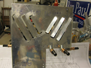
Here's a picture of the tunnel mod we finally settled on. It's a little embarrassing to think how much time was spent doing this. The benefit will come if we ever need to access where the fuel line come out of the tunnel.


As you may know, I've been kind of consumed with the idea of rolling my own lights with LED's. So while I was at Sun n' Fun a few weeks ago, I snapped a couple pictures of interesting applications. I'm still fussing over how I want to do ours.
Tonight I worked at my tube bending technique. Still needs work.
The 21' of new tubing and the screws I ordered have arrived. I am not too sure about the tiny little allen heads. I'm afraid I may break an allen wrench if I have to torque on these to get them set.

I bought a plastic covered piece of shelving material for laying up our roll bar. The board is really stiff. I think it will work well. I was glad that Bob and I were working together; instead of 'close enough' We came close to breaking out the micrometer.

Here's a picture of the tunnel mod we finally settled on. It's a little embarrassing to think how much time was spent doing this. The benefit will come if we ever need to access where the fuel line come out of the tunnel.


As you may know, I've been kind of consumed with the idea of rolling my own lights with LED's. So while I was at Sun n' Fun a few weeks ago, I snapped a couple pictures of interesting applications. I'm still fussing over how I want to do ours.
Tuesday, March 2, 2010
We continue to work
Most recently Bob has been working on the center section between the fuel selector and the firewall. He has devised a plan to modify the access panel below the cabin heat distributor box. He is working on the finer points of that.
Last night I was working on the rudder pedals; installing the cotter pins in the castle nuts. Also, getting the brake lines ready for installation. I still wrestle with the idea of spending more money for better brake lines, but see lots of big ticket items still looming on the horizon.
I've been researching LED's and how to design the wingtip lighting.
Also, I've been reading up on the roll bar and how it goes together. I need to come up with a board that will be suitable to clamp the roll bar down and keep it straight.
We are often anxious to make better progress, but take solace in the knowledge that this is not a race. It is a hobby, and we are constantly learning new skills in the process of building. We can't help but be eager to 'gitter done'.
Thursday, February 11, 2010
Heater
Bob is working on the pieces that will become our cabin heater. It will also, be the cover for our fuel lines.
A welding we will go...
 We had an informative presentation about welding at the chapter meeting Tuesday evening.
 After the presentation, those that wanted could try their hand at striking an arc.
For myself, I found the information interesting, but I'm happy that I have friends who can weld.
Saturday, January 30, 2010
A visit to Catto propellers
My wife and I drove from Olympia to San Diego to take a cruise with the family in December. On the way South, I decided to drop the prop off at Catto Propellers to have the spinner cut for it.
 If you don't know where Mokelumne Hill, CA is; it roughly East of Sacramento. I had purchased a Tom Tom GPS to aid with my land navigation. I'm glad I did as it was able to guide me to the trail head of the one lane winding road that took us eventually to the factory. It's about a 15 minute drive once you find the trail. Here is what the terrain looks like.

My cell phone had lost contact with civilization and the GPS said I had left the road. So I wondered as I kept going up this winding ice covered road what I would do if something happened. Visions of survivor man were tripping thru my head. Can I start a fire?... I digress.
Anyway I had faith and wanted very much to meet Craig and visit the birthplace of our beautiful propeller.

I had found the entrance, but didn't have the code to open the gate.
Did I mention my cell phone was useless?
Fortunately, the neighbor let me use his land line to contact Craig and he let us in.
I don't think they get many visitors up here.

Since it's people that are really important let me introduce Craig.
Craig is very kind and knowledgeable.
He explained to me that he is in the process of expanding his operation to keep up with demand.
Each of the clipboards you see on the walls represents a propeller order.

There are two full time employees at Catto.
Nadine is the office manager.
She has been very helpful to me.

Manny is the wizard's apprentice and works in the factory.

Here are some of the rough-cut wooden cores.
After they are worked down to their finish cross section, there are two layers of carbon fiber and four layers of fiberglass applied.
The finished product is light, strong, and efficient.
Craig was telling me that many of the racers use his propellers.

As a part of the expansion, Craig was showing me this apparatus which is used to create a 3D digital model of the airfoil.
This will then be used to direct a three axis router.
This should ensure that every prop is exactly to spec and do it quickly.

So we left the propeller there and continued on to our vacation cruise.
On our way back, Manny was kind enough to meet us at the trail head
with our prop, spinner and extension plate.
Here's another VAF siting.
I am glad we took the side trip.

Our party included nine adults and seven grandkids.
Having the whole family together (for me)made it the best cruise so far.
 If you don't know where Mokelumne Hill, CA is; it roughly East of Sacramento. I had purchased a Tom Tom GPS to aid with my land navigation. I'm glad I did as it was able to guide me to the trail head of the one lane winding road that took us eventually to the factory. It's about a 15 minute drive once you find the trail. Here is what the terrain looks like.
My cell phone had lost contact with civilization and the GPS said I had left the road. So I wondered as I kept going up this winding ice covered road what I would do if something happened. Visions of survivor man were tripping thru my head. Can I start a fire?... I digress.
Anyway I had faith and wanted very much to meet Craig and visit the birthplace of our beautiful propeller.

I had found the entrance, but didn't have the code to open the gate.
Did I mention my cell phone was useless?
Fortunately, the neighbor let me use his land line to contact Craig and he let us in.
I don't think they get many visitors up here.

Since it's people that are really important let me introduce Craig.
Craig is very kind and knowledgeable.
He explained to me that he is in the process of expanding his operation to keep up with demand.
Each of the clipboards you see on the walls represents a propeller order.

There are two full time employees at Catto.
Nadine is the office manager.
She has been very helpful to me.

Manny is the wizard's apprentice and works in the factory.

Here are some of the rough-cut wooden cores.
After they are worked down to their finish cross section, there are two layers of carbon fiber and four layers of fiberglass applied.
The finished product is light, strong, and efficient.
Craig was telling me that many of the racers use his propellers.

As a part of the expansion, Craig was showing me this apparatus which is used to create a 3D digital model of the airfoil.
This will then be used to direct a three axis router.
This should ensure that every prop is exactly to spec and do it quickly.

So we left the propeller there and continued on to our vacation cruise.
On our way back, Manny was kind enough to meet us at the trail head
with our prop, spinner and extension plate.
Here's another VAF siting.
I am glad we took the side trip.

Our party included nine adults and seven grandkids.
Having the whole family together (for me)made it the best cruise so far.
Engine has arrived

I approached Gerber Collision and Glass about the possibility of having the engine delivered to their loading dock. I'm pleased to announce that Kirk was willing to do that. Very kind! In talking with him I think that he has an love of flying too. He seemed keen to talk airplanes with me.

Anyway, I called for a few volunteers to help with the lifting.
Here they are:Boyd on the right, Rich in the foreground and Bob in the blue jacket on the left.
While I was gathering timbers to slide it into the truck, they just picked it up and set it in.
From Gerber's loading dock to the Brooks Aircraft factory floor took only twenty minutes. I was there to help take it off the truck. Take it from me; it's HEAVY.

Bob and I spent some time looking through all the printed material and assorted parts.
Wednesday, January 6, 2010
Brake return springs installed

I saw this mod on another builders site and on RivetBangers and liked it. It was simple to implement and only cost 12$ for the materials to do all 4 brake cylinders.
These are the McMaster part numbers and descriptions:
6389K625 - NYLON BEARING, FLANGED, FOR 3/8" SHAFT DIA, 1/2" OD, 3/8" LENGTH
9657K115 - STEEL COMPRESSION SPRING, ZNC-PLTD SPRING-TEMPERED, 3" L, 1/2" OD, .047" DIA
9946K13 - ALUMINUM SET SCREW SHAFT COLLAR, 3/8" BORE, 3/4" OUTSIDE DIAMETER, 3/8" WIDTH

This is how they look assembled. You'll notice that I also replaced the multiple washers with a piece of round UHMW I purchased. The material is very cheap and fairly easy to work with. I simply measured how long it needed to be and then drilled the appropriate size hole and cut to length. If I do say so myself, I think it way cooler than 4 or 5 washers looking like we really weren't sure what we were doing.
 Last night I noticed that the elevator push rod was in a bind with the flap actuator attachment.
 There were two different parts that could be used for this. We cogitated over them and chose the one we thought looked stronger without realizing the bind it would create. I took remedial action and removed the extra material.
Not a problem, but I'm glad I caught it.

Proceeded laying up the the tunnel cover F-741B.
I confess with humility my envy when I read of other builders spending two hours for some major task.
Then this little cover takes us the better part of an evening.

Here Bob does the countersinking.

And voila; the finished product.
Engine is ready to ship. Unfortunately, I need to have a loading dock to get it delivered to Olympia. Otherwise, they want me to pick it up in Tukwilla (45min drive).
I think I'll have to find a loading dock.
Subscribe to:
Posts (Atom)
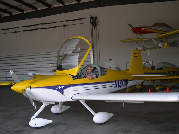
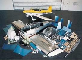
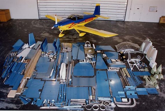
Before we decided to build an RV9A we were looking at the RV7A. This picture was taken on a factory tour.
Standard (aka Slow build) RV9a kit
Quick build RV7 kit