Introduction - N9XG
We're building an RV9A together. The tail number is already reserved and is "N9XG"
It's the biggest project either of us has ever started. We're having a lot of fun and learning many things about airplane construction and about ourselves as well. This site is about the process, and our progress.
We will be updating this from time to time with progress reports. If you can't see enough detail in any of the pictures you can click on them and they will expand (like Magic).
Started attaching the bellcranks last night and boy am I confused!
It looks to me like the Left belongs on the Right wing and vise versa. Have emailed Vans for advice. Take a look.


The second picture show it sitting on the spar in the Left wing. But something is not right. As I understand the function, the push rod moves the bellcrank causing a vertical move of the other end bearing, but I don't think this will work.
For purposes of orientation, the fuselage is to the right and the wing tip is to the left as you are viewing the picture.
Well I got confirmation from Vans. The part labeled "L" goes on the right wing and the part labeled "R" goes on the left wing. I just got confused, I guess.
Gee I didn't realize it had been so long since I posted an update. We have not had as consistent a schedule during the holiday season as we need to maintain progress. Never the less, we continue working. We have fabricated numerous pieces and parts as directed by the plans.

We have purchased compartmentalized boxes to hold the numerous different sized bolts, screws, rivets, washers, nuts, pins, nut plates and such.
The push rods (elevator and aileron) are all done and ready to assemble. Thanks to Doug Drees the small push rods that connect the bell crank to the ailerons have welded connections. They look really nice.
The picture is of the aileron attach points. You can see a larger picture if you click on it.
I contacted Craig at Catto props to see when that will be finished. He thinks 8 weeks. So we'll have it in plenty of time...
We insulated the garage door with 1 1/2 inch styrofoam sheets. The garage is now kept comfortably warm with just a small heater which is left on 24x7. It's gratifying to see that the snow on the roof doesn't melt. That means my insulation is working.
I screwed up on two parts and had to purchase replacements. But it only cost about $20. So all that was harmed was my pride. This is the elevator bell crank.

Got the flaps and ailerons hung up on the wall and off the floor. Mounted a small grinder with a scotch brite wheeel on the bench to make it easier to clean up parts.
Tidied up the shop some and continued work on attach points for the ailerons. The grinder is much faster than doing it by hand. The aileron push rods are ready to install.
Also had some company. Alex and his wife Sophia (newly weds) came out to see the project. Alex seemed pretty interested, maybe a little overwhelmed. He kept saying things like "Awsome", "WOW", and "This is so Cool!" Nice when men can agree...
Yesterday the mirrored acrylic sheet arrived. I ordered it for the wing tip lighting. The sheet is 12" x 24" and cost about 14$ total. It is twice as much as I need (unless I mess up a lot). The landing lights are on order too. They will be HID fog lights from Harbor Freight. I still need to order the strobes, and the LED lights and drivers.
John from church came to help last night. We cut the push rods that actuate the ailerons. We also got about half of the drilling done for the end pieces. They get connected with pull thru rivets. I was so glad I kept the inventory list. It was the only way to identify the rivets. The rivets are called out on the plans, but the y are in a bag that is labeled with a number. The only connection is the inventory list.
Bob was working on the flaps; specifically where they connect to the wing.
It was a good build night. Good company, fun, and progress.
Last night I had a little time on my hands so I opened the bag of parts for the electric flaps. There are lots of little parts; nut plates, bolts, angles, connectors, wire, a big dog servo and a few pages of instructions. Don't you love the minimalist approach to directions?
Anyway, I started marking some of the angles and flat aluminum. They need to be marked, drilled, cut, ground, etc before we actually start the installation.

This is the TruTrak ADI Pilot II.
It is by all accounts a very cool tool. It looks like this will be in our panel.
•GPS-Slaved solid-state DG
•Digital Ground Track Selector
•GPS Nav Mode
•True Control Wheel Steering
•Altitude Hold
•Altitude adjust fro baro change
•Built-in ADI:
Bank angle is instantaneous gyro data. Pitch is gyro enhanced vertical speed. Direction is an electronic DG showing track. Extreme bank angle is enunciated by flashing red arrows which indicate required stick motion to correct unusual altitude. Low airspeed warning is enunciated by flashing A-S on the display.
•12-28 Volt only
•ADI Pilot II 3-1/8" Dimensions
3.4" H x 3.4" W x 4.7" D
•Standard weight including servo 6lb

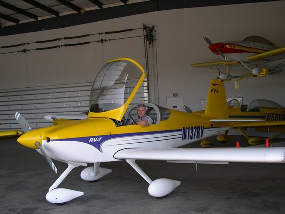
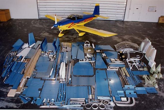
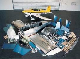
It occured to me that I have not posted any picture recently. Here are a couple shots of the quick build fuse and wings.

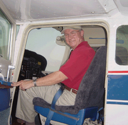
And a picture of Bob holding one of the wing tips.
We've been trying to decide how to do the lighting. Should we put the landing lights in the wing tips or cut out a section of the leading edge of each wing?
Still cogitating on that...
Here are a couple of solutions we've looked at:
CreatiAir Very Nice Look One of the advantages of LED lighting is it takes very little power to drive them. Price may be the winning factor.
As you can see these solutions are not what you could call cheap.
One last trip to get the correct rivets and this time's the charm Installed rivets to left elevator. As it turns out our sequence was a little off. The cherry max fit great but there was no way to get the pop rivet tool to one of the rivets, so we ended up bucking it after all.
Then fiddled with the hinge pin for the trim tab. Had to do some realigning of the hinge as it was slightly bent in the riveting mentioned above. No big deal. The hinge pin is steel and fairly stout, so putting the proper bends in the end was an imperfect operation.
After we patted each other on the back we decided to fit the fiberglass pieces to the ends of the elevators. Had to trim some of the fiberglass to get the proper fit. Band saw made short order of that. Also got an opportunity to fire up the dremmel. We proceeded to drill and cleco around the the ends. Went very well.
Then we started fitting the lead counter balance weights for the elevators. I don't know why we didn't do this stuff while we were waiting for the QB fuse and wings... Oh well. If we keep moving, we'll get there.
I continue reading about the work that's ahead of us. It's so helpful to look at some of the better builder's sites. Pictures, descriptions, solutions, creative ideas, etc. This is a great learning experience.
I made a special trip to Puyallup to get just a handful of cherry max rivets. It's all that's left to say "Done" to the empennage. Cherry max rivets are very specific about size, but they are the only choice for a structural pull-through rivet. I even took the parts with me to be sure I got the right rivets. The young guy minding the store seemed so sure of himself that I didn't even question him. Bad move!
I got home and it was painfully obvious that I had the wrong rivets. Lesson learned.
We have spent weeks cogitating over avionics and options. Reviewing the quick build fuselage and wings to know what has and what has not been done. It was starting to feel like we would never get back to building. But Monday evening we got back in the game and drove some rivets. It was great to be back in the building mode.
There ate still lots of questions that need answering. What's going in the panel? What brands do we want to purchase: EFIS, EIS, NAV/COM, GPS, etc. It may come down to price; It takes my breath away to see how fast the panel can get REALLY expensive.
Tony Partain is on deck and ready to deliver our order. Vans called today to let me know the Fuse and Wings are in(June 17). Payment's in the mail yesterday and the shop is ready.
In the interim we have to finish the L. Aileron and trim tab. Bob needs to finish up his private pilot license. We need to rearrange the shop to accommodate the new parts.
We've also talked about possibly starting the fiberglass work on the tail, but neither of us has experience with that(yet).
How exciting! Of course it won't arrive for a while. They don't have them in stock so we will have a little time to clean the shop, sharpen tools, and get ready for the day Mr. Partain delivers the goods to my door.
We are finishing up the elevators. The right elevator trailing edge was JB Welded Wednesday and this evening I opened it up and started cleaning the excess material.
It looks very straight and I'm very pleased with the product.
Last night we finished off the rudder. The trailing edge turned out very nice. Thanks to Jim Triggs and Paul Westcott for their help and advice. Jim suggested using JB Weld to lock the wedge together with the skin before we riveted.
It worked great! Here is a picture of the assembly curing. In addition to the JB Weld we match drilled two pieces of aluminum angle and clecoed it all together to keep a nice straight edge.


We also added a reversed wedge to make it all fit together well. You can click on the image to see more detail. Our first application of JB Weld had a few spots that didn't bond. So we reapplied the JB Weld and heated the mix to make it flow better. It worked well.
Last night we formulated a plan for how we would apply the JB Weld to the trailing edge. We are both feeling a little tentative since we have no experience at this. We have a plan though and we have a test joining of two pieces of scrap aluminum. Stay tuned, I will take pictures of the process.
A word of caution. JB Weld is a nice strong adhesive for metal. It takes about 24 hours for it to set up. We learned the hard way that it's important to use saran wrap to keep your clecoes from becoming welded to your work. If you cover the welded area with saran wrap before you clamp it removal of the clecoes is no big deal, but if you don't use saran wrap, I wish you luck on extricating your clamps from the work without buggering up the part. At the very least you will have to destroy some of the clecoes. Trust me!
Last night was spent preparing for finishing up the Rudder. We match drilled two pieces of aluminum angle to hold the trailing edge together. The trailing edge is nice and straight when the angles are attached. I hope it holds that line when we start putting the rivets in.
We also called a couple of mentors to see how they did the trailing edge. We talked about pro-seal and settled on using JB weld. I've never used either one so I'm a little nervous. JB Weld is pretty cheap; about $5.00 for the two tubes. I gather they get mixed together before it's applied.
Tomorrow I will make a trip to the airport to get a couple nylock nuts for the counterweight. Once it is secured we can press on to the finish with the rudder. We are both pleased with the way things are shaping up, but we would like to be moving faster...
The Process
Most of us think of the airframe as the main thing, and I suppose it is; since you can't fly without it. The kits that Vans sells are match hole punched. That means that the holes are already located and punched when you get them. This saves a lot of time as you can imagine. So what follows is what you do once you've unpacked and inventoried the parts from the factory.
There are several thousands of these planes flying. Rather than making mistakes first-hand, I recommend looking at the web sites of builders who have already done this. Some of my favorite links are provided. You should also look at Van's 'Links' page for the model you're building.
Before touching the parts, it is advisable to read the instructions and review the drawings until you have a clear idea what needs to happen and what sequence it needs to happen in. The drawings are invaluable.
Each sub assembly requires the same basic process:
1. Prepare the parts for fitting. This entails cleaning, filing, and finally scotchbrighting. In addition, some parts require fabrication and/or machining.
2. Fitting is done numerous times. The pre-punched holes are matched to the corresponding part(s) and are held together with clecos.
3. Match drilling is done in assembly to provide optimum fit.
4. Once the holes are match drilled to the proper sizes, the part is disassembled and deburred to remove any sharp edges and irregularities that might result in a poor fit or the development of a crack.
5. Rivets that will be flush with the skin require either a dimple or countersinking. This is normally obvious, but sometimes the rivet needs to be flush and it's not clear at first glance just why.
6. At this point, a coat of primer and (in some cases) paint is applied protect the metal from corrosion. We've decided to prime and paint all skeletal parts; i.e. Spars, Ribs, etc. Skins will be primed where they connect. The method to our madness is this; we want defects to appear first in the skin where they are easiest to fix and pose less of a threat.
7. This is a dangerous part of the process because you might want to rivet something. But WAIT! Review the plans and the directions again.
8. Okay, so you've reviewed the plans and the parts are ready to assemble. Double and triple check the plans to ensure that the proper rivets are used. It's easy to mess this up or get out of sequence.
Rivets and Riveting
There are thousands of rivets that hold the plane together. Since this is an important task, let's talk a bit about them.
The rivets we'll be using are made of aluminium and are set in one of several ways; Hammering, Squeezing, Pull through.
Hammering a rivet is best done with a partner. One person operates the rivet gun and the other holds a bucking bar on the back side to create a shop head. I've tried doing this alone and almost always with undesirable results. The idea is for the shop head to be approx 1.5 times the diameter of the shank of the rivet.
Squeezing a rivet requires a special tool and is my preferred way whenever possible. Some folks use a manual squeezer, but I like pneumatic squeezer. They develop approx 3,000 pounds of force in the last 1/8th inch of the piston's travel. So proper adjustment is important. Once adjusted properly it will deliver consistent rivet sets.
Pull through (aka Blind or Pop) rivets are for those applications where there is no way to get access to the back side of the rivet. In general this type of rivet has inferior strength characteristics compared to a solid rivet. The noteworthy exception is the Cherry Max rivet. It is a pull through rivet, but it is also structurally rated and not cheap.
Removal
When rivets are set badly (as is sometimes the case) You need to decide if it's so bad that it just has to be replaced or is it okay as is. The main concern is to remove the offending rivet without doing damage to the hole it's in; e.g. enlarging or elongating or both.
If it just doesn't pass muster, get a drill bit about the diameter of the rivet shaft or smaller. Center punch the head of the rivet (solid rivets only) and then carefully drill thru the head just down to where the shaft meets the hole. Once this is done, insert and old drill bit into the hole and wiggle the head until it snaps off. Once the head is off you should be able to push it out with a punch.
With pull through rivets this can be problematic, as the shaft is most likely steel and may turn with the drill bit. Another problem with removing blind rivets is this. Blind rivets are used because access to the back side is either difficult or impossible. Onc you commit to removing the blind rivet, you have to figure out how to remove the back side when you punch it thru the hole.